
Gas Porosity And Surface Die Casting Defects
- Hill and Griffith

- Jul 26, 2017
- 4 min read
NADCA EC-515 Die Casting Defects Course Review, Basics for controlling die casting defects - By Dr. Steve Midson
Gas porosity is the biggest single problem in die casting. High gas content prevents heat treating or welding and makes strength unpredictable.
There are three major sources of gas porosity for die castings: Trapped air, Steam, Gas from lubricant
Gas porosity is round and generally smooth, although it can be flattened to some extent by pressure
The actions to reduce gas porosity, in general, are not the same as the actions for reducing shrink porosity

Any turbulence in the metal movement that allows some air bubbles to be trapped in the metal – These bubbles will remain trapped when the casting solidifies
Air can be trapped in: Shot sleeve, Gating system, Die cavity
Starting with the shot sleeve, we will review potential sources of trapped air and possible corrections

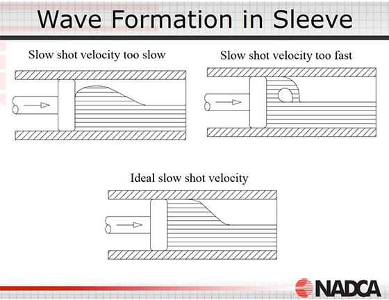
If the wave is met by the tip as it moves forward, then extra splashing and sloshing is generated, and this captures some bubbles. However, if the tip is started forward just after the wave has been reflected from it, then the tip “chases” the wave, and this will give the best chance for minimizing air entrapment
The timer that sets the time delay between the end of pour and the start of shot will determine when the tip starts forward in relationship to this wave
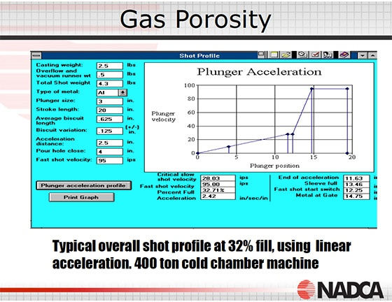
The next part of the sequence that can add trapped air (bubbles) and porosity is the acceleration of the plunger to the slow shot speed • This acceleration rate should be slow enough to keep the metal from tumbling over (surfing), and fast enough to prevent trapped air between the generated wave and waves reflected from the die
This acceleration rate will vary with the percent fill and the length of the sleeve, but the usual range will be between 2 and 2.8 inches per second per inch of travel
The optimum acceleration profile can be closely approximated by a straight line (linear acceleration) when the sleeve fill is below about 50% (which is where most of the problems occur)
Above about 50% fill, the optimum acceleration trace will be more of a curve
Using these methods, the acceleration will normally cause the plunger to reach the critical slow shot speed 1 or 2 inches before sleeve full
This is very close to the start of fast shot, so there is little time to spend at the slow shot speed
The trace shown on the next page is for a fill percentage less than 50%


Once the metal starts to enter the cavity, it will normally flow at a high velocity, very turbulent flow condition, and will trap some of the air present as gas porosity
The flow pattern design should be such that the metal tends to push the air through the cavity to the vents
Much of the air in the shot sleeve and the cavity can be pushed out the vents or the vacuum system
Vents must be sized correctly and go to the edge of the die if they are to be effective
Vents must be kept clean of flash & lubricant buildup
To summarize, the control of trapped air porosity will involve a check list like the following: – Plunger control settings: Pour rate, Delay before shooting, Pour hole speed, Start slow shot point, Slow shot speed, Fast shot start point – Runner area: No square corners, No low or high ejector pins, Decreasing runner area in the metal flow path – Cavity: Vent location at last place to fill, Vents sized right and go to edge of die, Vents to be kept clean
Steam is the second source of gas porosity
Steam comes from water on the cavity surface when the metal arrives
This gas is mostly trapped in the metal because there is little chance to push the gas out the vents - the gas is not present until the metal arrives, and so is mixed with the turbulent metal flow as soon as it is generated
The water is mostly from the die spray but it can also be from other sources
Some of the water will evaporate from a hot die, but you cannot count on this happening
Therefore, it is critical that the die be dry when it is closed
Other sources of water on the die: Leaking water lines, Dripping overhead sprayers, Leaking hydraulic cylinders

Checklist to reduce gas porosity from steam: To much water based die lubricants on the die (the die must be dry as it closes), Leaking water lines, Leaking water pipe connections, Crack in the die into a water line, Sprayer dripping on the die as it closes, Water glycol hydraulic fluid getting on the die
The third source of gas porosity is lubricant
The lubricant used on the dies or on the plunger can generate gas when heated by the incoming metal
This gas (like the steam) is only formed when the metal arrives, and so it is not possible to force most of the gas out the vents ahead of the metal flow
All lubricants give off some gas when heated to the temperature of the molten metal - the amount and type of gas will vary from lubricant to lubricant
The biggest single lubricant source of gas porosity is the plunger lubricant
The usual problem is that the lubricant is applied ahead of the plunger much heavier than is needed
This is especially true when a dragging or worn tip is nursed along with extra lubricant
Check list of actions for gas porosity from lubricants: Check the amount of plunger lubricant, Reduce the die spray lubricant, Look for pockets where the lubricant can accumulate on a cold die
(Thanks to All About Metallurgy for posting this PDF. We'll cover other aspects of die casting defect control from the course in upcoming blog posts)
(If you liked this article you might also like this post on, "Die Casting Defects")


Comments